Connect the second modular SATA Cable
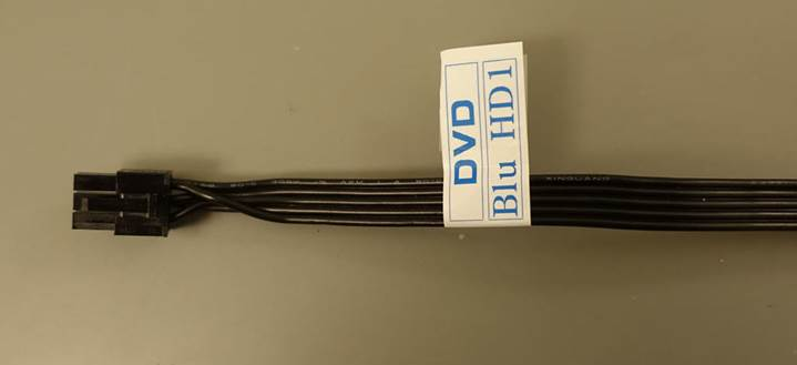
Next, label the second SATA power cable.
Make a label that reads DVD-Blu HD1
Fix the label next to the SATA connector that goes into the Power Supply Unit.
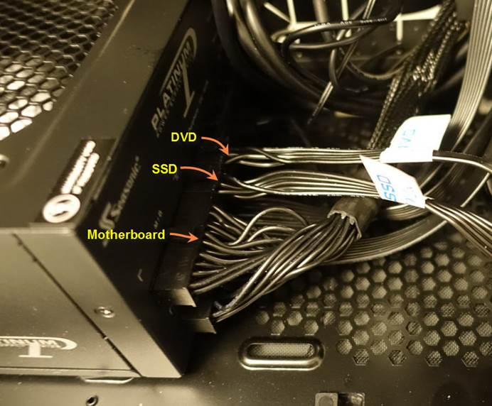
Use the slot marked blue in the picture below to plug in the second SATA Power Cable labeled DVD-Blu HD1.
The first SATA Power Cable that feeds the SSDs goes right next to the large Motherboard connector.
The second SATA Power Cable that feeds the DVD and Blu-ray sits right next to it.
You can see why it is a good idea to label all the cables.
It can become a mess very quickly.
Plug in the 3 SATA power connectors as follows.
Connector #1 = DVD
Connector #2 = Blu-ray
Connector #3 = No connection
Connector #4 = HD1
Connector #4 supplies power to HD1.
Notice that Connector #3 is not connected to anything.
It is being unused.
However, there is a way to utilize this power connector.
Examine the 3 Case Fan Headers that come standard with the Define R5 Case, and the corresponding SATA Power Header that supplies power.
Originally you had the 2 Front Fans connected to 2 of these Case Fan Headers.
If you want to go with that plan, you must attach Connector #3 to the SATA Power Header for the Case Fans.
Here is how you would proceed to make the connection.
This picture shows Connector #3 inserted into the SATA Power Header for the Case Fans.
Under this configuration, the speeds of the 2 Front Intake Fans are controlled by the Case Fan Switch on the front panel.
It gives you 3 manual Speed Settings:
· Low
· Mid
· High
You can get far better control of your Fan Speeds by connecting them directly to the Motherboard while using ASUS Q-Fan Control.
This is what you have now.
Leave it the way it is.
This completes your SATA Power Connections to all your SATA devices.
Next, you will connect the SATA Data Ports to your Motherboard using individual SATA Data Cables.